
CH 1 Introduction
CH 2 Aircraft and Systems Description and Operation. CH 2 : 2.1 ~ 2.33
The following information and pictures based on :
- 1.Boeing AH-64A Apache Attack Helicopter. Technical and Operator's Manual (Unclassified).
- Aviation Unit And Intermediate Maintenance Manual.
- Aviation Unit And Intermediate Maintenance Repair Parts And Special Tools List For Helicopter.
- Ultimate Factories : AH-64 Apache.
- Website, Military Forum, Youtube.
CH 1 Introduction
1.1 General
1.2 Warnings,Cautions, and Notes defined
Warnings, Cautions, and Notes are used to emphasize important and critical instruction and are used for the following conditions:
The pilot usually occupies the rear seat while the front seat is the co-pilot/gunner; however all weapon systems can be fired from either position.
CH 2 Aircraft and Systems Description and Operation
2.1 General
The AH-64 Apache helicopter is a twin engine, tandem seat, aerial weapons platform.
2.2 Introduction
Slip over
2.3 General Arrangement
Look the following figures.
2.4 Fuselage

The fuselage includes a forward, center, and aft section. All major weight items
(crew, fuel, and ammunition) are supported by bulkheads, frames, and a longitudinal support structure.
The " forward " fuselage section contains a portion of the Extended Forward Avionics Bays (EFAB), and the CPG station. The Target Acquisition and Designation Sight (TADS),
Pilot Night Vision Sensor (PNVS), and a 30mm area weapon are also mounted to this section.
The " center " fuselage contains a portion of the EFAB, the pilot station, and provides support for the main landing gear, main transmission, wings, fuel cells, and ammunition bay.
The " aft " fuselage section includes the vertical stabilizer and mounts the tail landing gear. The aft avionics bay and stowage compartments are contained in the aft section. The tail rotor,
drive shafts, gearboxes, and stabilator are attached to the aft section.

2. Vertical Stabilizer
3. Air Data Sensor
4. TADS and PNVS. Target Acquisition and Designated System. Pilot Night Vision System.
5. Canopy Jettison Handle Access Door
6. Forward Avionics Bay Access Door
7. Mooring Lug Access Door
8. Fire Extinguisher Access Door
9. Intercommunication Access Door
10. Main Transmission Oil Level Sight Gage Access Door
11. Aft Equipment Bay (Catwalk Area) Access Door
12. Hydraulic Ground Service Panel Access Door
13. Hydraulic Oil Level Sight Gage Access Door

14.Infrared Countermeasure Device Mount
15.Chaff Payload Module Mount
17. Aft Storage Bay Access Door
18. Survival Equipment Storage Bay Access Door
19. Main Landing Gear

21. Co-Pilot Gunner Door
22. Searchlight
23. Ammunition Bay Access Door
24. Tail Landing Gear
25. Aft Avionics Bay Access Door
26. APU Oil Level Sight Gage Access Door
2.5 Rotor
The helicopter has a fully articulated four-blade main rotor system equipped with elastomeric lead-lag dampers. The tail rotor is a semi rigid design and consists of four blades.
2.6 Engines
The helicopter is powered by two horizontally mounted turboshaft engines. Power is supplied to the main transmission through engine mounted nose gearboxes, shafts, and over-running clutches. The main transmission drives the main and tail rotors and accessory gearbox.

2.7 Wings
Left and right wings are attached to the center fuselage. Each wing provides two hard points for
external stores pylons with hydraulic and electrical quick-disconnects.

2.8 Special Mission Kits
The helicopter can be equipped with a Longbow kit, infrared (IR) jammer kit, radar jammer kit,
radar warning kit,laser warning kit, winterization kit, chaff kit, and extended range kit.
2.9 Principle Dimensions


2.10 Turning Radius and Ground Clearance

2.11 Danger Area
2.11.1 Approaching Operating Aircraft
2.11.2 Tail Rotor Airflow and Main Rotor Down Wash
2.11.3 Exhaust Gases
2.11.4 During Canopy Jettison
2.11.5 Laser
The laser must be given special safety considerations because of extreme danger involved during its operation. Relatively low laser light levels can cause permanent damage to eyes and skin burns.
2.11.6 Environmental Control System Exhaust
High temperature, high velocity air is exhausted from the rear of both EFABS. Personnel should remain clear of these exhaust areas when working on or around the helicopter.
2.11.7 HF Radio Antenna
2.12 Crew Stations
The crew stations are arranged in tandem and are separated by a ballistic shield.The canopy
frame and transparent ballistic shield forms a rollover structure.

2.13 Crewmember Seats

2.13.1 Seat Height Adjustment
Vertical seat adjustment is controlled by a lever on the right front of the seat bucket. When the lever is pulled out (sideways), the Pilot seat can be moved vertically approximately 5 inches and locked at any 5/8 inch interval, the CPG can be moved vertically approximately 3 3/4 inches and locked at any 5/8 inch interval. Springs counterbalance the weight of the seat. The lever returns to the locked position when released.
2.13.2Inertial Reel Operation
A two position shoulder harness inertia reel lock lever is installed on the left front of each seat. When the lever is in the aft position, the shoulder harness lock will engage with an acceleration of 6 Gs in any direction and/or if the webbing is exposed to an acceleration of 2-1/2 Gs or greater. In the forward position, the shoulder harness lock assembly is firmly locked. Whenever the inertia reels lock because of deceleration forces, they remain locked until the lock lever is placed in forward and then aft positions.
2.14 Controls, Displays, Instrument Panels and Consoles
The following figures provide an overview of the cockpit.
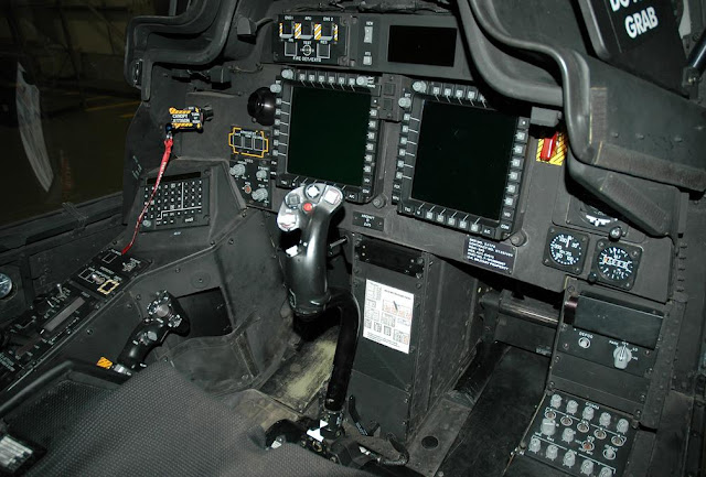
Cockpit


Cockpit Gunner


Co-Pilot Gunner Station Diagram
1.
2.
3.
4.
.
25.
26. Boresight Reticle Unit
27. Optical Relay Tube
28.

1. Canopy Door Release Lever
2. Multipurpose Display Unit
3. Master Zeroize
4.
5.
6.
7.
8.
9.
10.
11. Cyclic Stick
12.
13.
14.
15.
16.
17.
18.
19. Collective Stick
20.
21.
22.
23.
24.
25.
26.
27.
28.
29.
30.
31. Bore Sight Reticle Unit
32. Master Warning
33.
34.
2.15 Main Landing Gear

trailing arms transfer the helicopter landing and static loads to the airframe, and the shock struts absorb vertical loads.

shock struts are attached to mounts on the fuselage structure. In addition to its normal energy absorbing function, each shock strut has one time high impact absorbing feature. it shear rings are sheared and a rupture disc bursts causing a controlled collapse of the strut.


2.16 Tail Landing Gear
The tail landing gear consists of two trailing arms, nitrogen/oil shock strut, fork, axle, and wheel.
The shock strut has an impact absorbing capability similar to that of the main landing gear
shock strut. The tail wheel is 360 degrees swiveling for taxiing and ground handling. The tail
landing system incorporates a spring loaded tail wheel lock. The tail landing gear is
hydraulically unlocked from the crew station or manual locked/unlocked by a ground crew using
a handle attached to the actuator.


Tail Landing Gear Assembly

Wire Strike Protection Installation, Tail Landing Gear


Landing Gear, Fixed Tail Landing Gear Subassembly (Fork and Arm)
2.17 Landing Gear Brakes
The brake system affects only the main landing gear wheels. The main landing gear system
consists of two hydro-mechanical systems, one left and one right. Braking action is initiated
from either station by applying foot pressure at the top portion of the directional controls pedals.
This actuates the master cylinder attached to each brake pedal. The master cylinders
pressurize hydraulic fluid in the master cylinder system components. The pressure is transmitted through tubing to the transfer valves, and the parking brake valve, to the wheel brake asseblies. It actuates pistons in each wheel brake assembly causing fraction linings to move against floating brake disc to stop wheel rotation.

Brake System Installation (Master Cylinders)


Brake, Single Disk
2.18 Windshield and Canopy
The windshield consists of two heated, laminated glass windshields. One is directly forward of the CPG; the other is directly above his head. The canopy consists of five acrylic panels: two on each side of the crew stations and one directly above the pilot. The two canopy panels on the
right side are independently hinged. They latch and unlatch separately by interior and exterior handles. They swing upward and outward to provide entrance to, and exit from, the pilot/CPG crew stations. Failure to properlyclose either canopy will cause an advisory message to appearon the Up Front Display (UFD)/Enhanced Up Front Display (EUFD). The two canopy panels on the left side are fixed and do not open. Refer to Section II of this chapterfor information about the canopy jettison system.

2.19 MIL-STD-1553B MULTIPLEX (MUX) BUSES
MIL-STD-1553B MUX bus channels are employed for transfer of data between the various elements of the avionics system. Each channel is redundant, for failure and damage tolerance, and consists of a primary and secondary bus routed separately within the aircraft. MILSTD-
1553B specifies a one megabit per second, serial, command/response, multi-access data bus which uses a bus controller, remote terminal command/response protocol. The redundant System, Weapon, and Display Processors are each connected to two bus channels to facilitate control, monitoring, communications, and processing functions. The avionics are connected to the MUX buses in a manner which assigns related equipment to a common bus.
2.20 Multipurpose Display
The MPD provides the capability of controlling most of avionics system, and serves as the
primary targeting display for the FCR. The MPD allows a crew member to customize the way
he monitors aircraft and weapons system during the mission. The MPD is a color active matrix
liquid crystal display (AMLCD).


Multipurpose Display
The MPD is an interactive display through which systems can be controlled via bezel buttons or
the remotely located cursor controllers.
2.20.1 Eyewear Restrictions
MPDs emit polarized light. Polarized sunglasses should not be worn by the operator, because
they could make the display appear black. Sunglasses which preferentially block certain colors (such as yellow or green tint glasses) should not be used. Neutral density gray sunglasses are compatible with color displays. The MPDs are compatible with glasses and visors which protect against the aircraft’s own laser. However, use of other laser protective visors should not be attempted until their compatibility with all MPD format colors has been established.
2.20.2 Cleaning Restrictions
The MPDs should be cleaned with a clean cotton cloth and alcohol. Ammoniabased cleaners shall not be used.
2.20.3 Response to Touch
2.20.4 Screen Save Mode
2.20.5 MPD Viewability Controls
- Brightness (BRT) Control
- Video Enhancement (VID) Control
- Day/Night/Mono Control
2.20.6 MPD Bezel Pushbutton Controls
2.20.7 MPD Button Control Affect
2.20.8 Interrupting a Process
2.21 MPD PAGES
MPD pages are selectable by actioning variable action bezel page buttons, fixed action buttons (FCR, WPN, TSD, A/C, COM, or VID), or the Menu (M) button. Most MPD formats and their component controls operate independently. The same page may be presented on more
than one MPD in the same crew station, or on one MPD in each crew station.
2.21.1 Subsystem Organization and the Menu Page
2.21.2 Automatic Paging (Autopaging) of MPD Formats
2.21.3 Switch Paging of MPD Formats
2.21.4 MPD Cursor Controller/Enter
2.21.5 MPD Cursor Operation
2.22 GENERAL STATES OF MPD OPERATION
Crewmembers are provided consistent display feedback to indicate the current aircraft states. In general, information is displayed by exception. If it is not relevant to the current task or conditions, it will not be presented. For example, engine instruments will not routinely be presented constantly on the MPD after engine startup. However, the system will provide the ENG page automatically if an emergency condition occurs. Similarly, controls for radios which are currently not installed are not presented on the MPDs.
2.22.1 MPD Color Application
2.22.2 MPD Status Indications and Readouts
2.22.3 Bezel Button/Label Not Selectable
2.22.4 Operation In Progress (OIP)
2.22.5 Command Failed
2.22.6 Data Field Presentation of Invalid or Missing Data
2.22.7 Bold Font / Characters
2.23 MPD PAGES DURING SINGLE DISPLAY PROCESSOR (DP) OPERATION
During single DP operation, the original four MPD pages within the aircraft are reduced to two, with the left MPDs of both crew stations duplicating each other, and the right MPDs of both crew stations duplicating the other. Once a display processor has been lost, it will not be recognized as functioning again for a minimum of 10 seconds. Upon determining a DP is operational again, the MPDs will retain the same formats as presented during single DP mode, but in normal DP appearance and functionality. As a result of the page changes resulting from the failure, any ongoing crew operations at the time of the transition will be aborted. KU scratchpad data will be lost. During single DP operation, the CPG’s cursor symbol graphic changes so it can be easily seen and separated from the pilot cursor, even if they are both in the home position or format center. The pilots cursor does not change. Both cursors are visible in both crewstations.
2.23.1 MPD Stale Operations
2.23.2 MPD Format Selection
2.23.3 MPD Format Appearance
2.23.4 MPD Format Control
2.24 Keyboard Unit (KU)
and operator validation feedback. The KU communicates with the display processor via the MUX bus. The KU consists of a scratchpad display, alphanumeric pushbuttons, calculator function buttons, special function buttons, and a scratchpad display brightness control. When there is no ongoing MPD data entry button operation, the KU can be used as a notepad to enter data.


Keyboard Unit (KU)
The KU scratchpad accepts up to 44 characters, and can display up to 22 of these characters at a time. If the scratchpad exceeds 22 characters, the remaining text can be scrolled in and out
of the scratchpad area using the left or right arrows. The scratchpad also presents an up to 9 character prompt followed by a colon. The scratchpad LEDs can be tested by selecting the A and + keys simultaneously.
2.24.2 KU Lighting
The pushbutton brightness is controlled by the interior lights primary knob. Scratchpad brightness is controlled by the knob on the lower left corner of the unit. When the KU has not been in use for a minute, the display is not illuminated. Pressing any button or actioning a
data entry key will illuminate the keyboard display.
2.24.3 KU Operation
The KU becomes active in response to MPD selection of a data entry button or if user input
is required when a reauthentication request is issued by a Tactical Internet security officer. A short prompt and colon are presented, indicating the anticipated data to be entered. No data is accepted by the system from the scratchpad until ENTER is pressed. Upon selection of ENTER, the DP reads the scratchpad data and determines its validity. If it is valid, this data is accepted and the scratchpad blanks. If it is invalid, the scratchpad data will flash. The next operator keystroke stops the flashing and allows the crew to edit the data.
2.24.4 KU Keys
The KU provides alphanumeric, decimal, plus/minus, backspace, insert (space), left arrow, right arrow, clear, multiply, divide, plus, minus, and enter/equals keys.
2.25 UP-FRONT DISPLAY (UFD)/ENHANCED UP-FRONT DISPLAY (EUFD)
lines of the display present VHF, UHF, FM1 and FM2 radio status. The last line presents total fuel quantity, transponder (XP) status, and local or Zulu time.
2.26 Emergency Equipment
[ BLK 1 Emergency equipment also includes Survivability Equipment - CBR Blower.]
[ BLK 2 Emergency equipment also includes Survivability Equipment - CBR Blower, Emergency Locator Transmitter and Underwater Acoustic Beacon.]
2.27 Canopy Jettison
The canopy jettison system is installed to provide a rapid emergency exit for the crewmembers. The transparent portions of the four canopy side panels can be jettisoned by means of a detonating cord installation. The system is controlled manually.
The CANOPY JETTISON handles are located in the upper left area of the instrument panel in each crew station. The handles incorporate a safety pin which is to be removed before flight. Canopy jettison is accomplished by turning the handle 90°, releasing, and pushing in
(TURN 90° PUSH). An external ground crew handle is located under a quick release panel directly forward of the forward crew compartment windshield. All four canopy side panels are jettisoned by activating any of the three jettison handles.

2.28 Stores Jettison System
NOTE
Only that crewstation arming the stores jettison panel can de-arm it. Once armed, eithercrewstation can activate jettison.
2.28.1 STORES JETTISON Panel.
Pressing one or more of the alternate action pushbuttons on the STORES JETTISON panel will illuminate the selected pushbutton(s) to indicate that the stores jettison function at selected stations is ARMed. Pressing an illuminated pushbutton a second time will cause that pushbutton’s light to be extinguished, indicating that stores jettison at that station is no longer ARMed. Pressing the recessed JETT pushbutton will cause stores to be jettisoned from
all ARMed stations. 65
2.29 Portable Fire Extinguisher
2.30 Engine and APU Fire Detection
2.31 First Aid Kits
2.32 Master Zeroize
2.33 Survivability Equipment
No comments:
Post a Comment