
Heat Suppression is the critical device to reduce the possibility of being hit by heat seeking
missile.
2.35 - 2.46
2.34 Engines
The T700-GE-T701 engines are front drive turboshaft engines of modular construction.
One horizontally mounted engine is housed in an engine nacelle on each side of the fuselage
aft of the main transmission above the wing. The engine is divided into four modules :
Cold Section, Hot Section, Power Turbine Section, and Accessory Section.

2.35Cold Section Module
The cold section module includes the main frame, diffuser and mid frame assembly, the inlet
particle separator, the compressor, the output shaft assembly, and associated components.
The compressor has five axial stages and one centrifugal stage. There are variable inlet guide vanes and variable stage 1 and stage 2 stator vanes.
Components mounted on the cold section are :
the Digital Electronic Control (DEC)/Electronic Control Unit (ECU)
History Recorder/History Counter, Ignition System, and electrical cables as well as
the accessory section module.


2.36 Hot Section
The hot section module consists of three sub-assemblies : the gas generator turbine,
the stage one nozzle assembly, and the angular combustion liner.
2.37 Power Turbine Section Module
The power turbine module includes a two stage power turbine and exhaust frame. Mounted on
the power turbine is the thermocouple harness, the torque and overspeed sensor.


2.38 Accessory Section Module
The accessory section module includes the top mounted accessory gearbox and the following
components : a hydro-mechanical unit (HMU), a fuel boost pump, oil filter, oil cooler,
alternator, oil lube and scavenge pump, particle separator blower, fuel filter assembly,
chip detector, oil/filter bypass sensors, oil/fuel pressure sensor,
overspeed and drive valve (ODV), and an air turbine starter.
2.39 Engine Cooling
Each engine is cooled by air routed through the engine nacelle. Airflow is provided by eductor
pumping action of the infrared suppressor. Fixed louvers on the top and bottom of the aft
portion and movable doors in the bottom forward portion of each nacelle accelerate
convection engine cooling after shut down. The movable door is shut by engine bleed air
pressure during engine operation and is spring loaded to open during engine shut down.
2.40 Air Induction System
The engines receive air through a bell mouth shaped nacelle inlet at the front of the engine.
Air flows around the nose gearbox fairing before entering the engine nacelle inlet.
From the inlet, air continues through canted vanes in the swirl frame where swirling action
separates sand, dust, and other particles. Separated particles accumulate by centrifugal force
in a scroll case. The particles are ejected overboard via a blower which forces them through
a secondary nozzle of the infrared suppression device. Clean air, meanwhile, has passes
through a swirl vane which straightens the airflow and channels it into the compressor inlet.

A bell mouth shaped nacelle inlet at the front of the engine. Note that movable doors in the
bottom forward portion of each nacelle accelerate convection engine cooling after shut down.

In front of the engine inlet, we can see the nose gearbox .

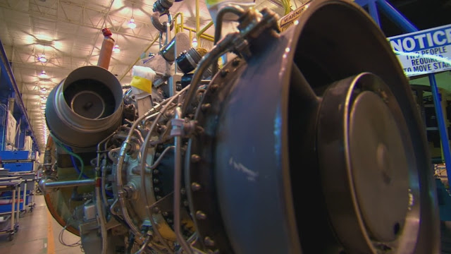

The Boeing technician installed the blower duct to the secondary heat suppressor.
Note that on the right side of the air turbine starter, air drawn through this door to cool the
engine.

Fixed louvers on the top of the aft portion has been covered.
2.41 Engine and Engine Inlet Anti-Icing System
To prevent damage to the engine, the engine anti-icing system should be manual activated
when the aircraft is flown in visible moisture and Free Air Temperature (FTA) is less than
5 degrees Celsius.
2.42 Engine Fuel Control
The engine has a conventional fuel control system : power control lever position and the
degree of collective pitch basically establish the power output demands place on the engines.
2.42.1 Fuel Boost Pump
A low-pressure suction fuel boost pump is installed on the front face of the engine accessory
gearbox. It ensures that the airframe fuel supply system is under negative pressure, thus
reducing the danger of fire in case of fuel system damage.
2.42.2 Fuel Filter
If this filter becomes clogged and impedes the passage of fuel, a bypass valve permits fuel
to bypass the filter.
2.42.3 Hydromechanical Unit
2.42.4 Overspeed and Drain Valve (ODV)
2.43 Engine Electrical System
2.43.1 Electrical Control Unit
2.43.1 Electrical Control Unit
The ECU controls the engine and transmits operational information to the crew stations.
It is solid-state device mounted below the engine compressor casing.
2.43.2 Engine TGT Limiter Function
2.43.3 Digital Electronic Control
2.43.4 Engine TGT Limiter Function
2.43.5 Hot Start Prevention
2.43.6 Fuel Pressure Warning System
2.43.7 Engine Alternator
2.43.8 Engine Alternator
2.43.9 Ignition System
Each engine has an ignition exciter unit with two igniter plugs. The exciter unit receives power from its engine alternator. The MSTR IGN keylock switch on the pilot engine power lever quadrant is an enabling switch to the ENG START switches. When an ENG START switch is placed to START, pneumatic motoring of the engine starter takes place and the ignition system is energized. Ignition cutout is automatic after the engine starts.
2.44 Engine Oil Supply System
Each engine is lubricated by a self-contained, pressurized, recirculating, dry sump system.
Included are oil supply and scavenge pump, an emergency oil system, an integral oil tank,
a filter, an oil cooler, and seal pressurization and venting. An inline chip detector, located down
stream of the scavenge pump, causes a caution message to be displayed if a metal chips are
detected.
2.44.1 Engine Emergency Oil System
Small oil reservoirs, built into the engine oil sumps, are kept full during normal operation by the
oil sump. If oil pressure is lost, oil will bleed slowly out of these reservoirs and be atomized by
air jets thus providing an oil mist lubrication for the engine bearings for thirsty seconds at 75%
Ng.
2.44.2 Oil Tank
Pertinent oil grades and specifications are in Section XV. The filler port is on the right side of the engine. The oil level is indicated by a sight gage on each side of the tank. Oil is supplied to the oil pump through a screen. The scavenge pump returns oil from the sumps to the oil tank through six scavenge screens.
2.44.3 Oil Cooler and Filter
2.44.4 Engine Chip Detector
2.45 Engine Starting System
The engine uses an air turbine stater for engine starting. System components consist of the
engine starter, a start control valve, an external start connector, check valves, controls, and
ducting.
2.45.1 APU Engine Start
2.45.2 Engine Bleed Air Start
2.45.3 External Source for Engine Starting
2.46 Infrared (IR) Suppression System
The IR suppression system consists of the primary nozzle and three secondary nozzles.
The primary nozzle is mounted to the engine exhaust frame and directs exhaust gases into
the secondary nozzle. The three secondary nozzles are attached and sealed to the engine nacelle. During engine operation, exhaust gases are cooled by the air drawn through the transmission area by a low pressure area created by the (Eduction Action) of the primary nozzle. The cooler air is mixed with the hot air in the three secondary nozzles cooling the exhaust gases.Angles of the primary and three secondary nozzles prevents a direct view of the hot internal engine components.


Angles of the primary and three secondary nozzles prevents a direct view of the hot internal
engine components.


If the engine catches the fire, the shutter can be shut off to extinguish the fire.
Amazing post ! It is good to see your post. I lot of great thing to learn. It is only because of you..Great man ! Would love to hear more things from your side..:-).
ReplyDeleteThank you for your admiration. But I did not take these photos.
ReplyDeleteThe photos of assembly of AH-64 captured from National Geographic
Megafactories. The other photos just download from websites.
If you were interested at aviation, you also can do it yourself.